 Overview
TraceCalc® Net design software brings you the latest advances in automated heat-tracing design capabilities. With its new intuitive and mobile-friendly interface, you can create a heat-tracing design quickly and accurately. Providing easy-to-use standard reports to help you obtain the best heat-tracing solution for your project.
 Index
Index
 Design ProcessIndex
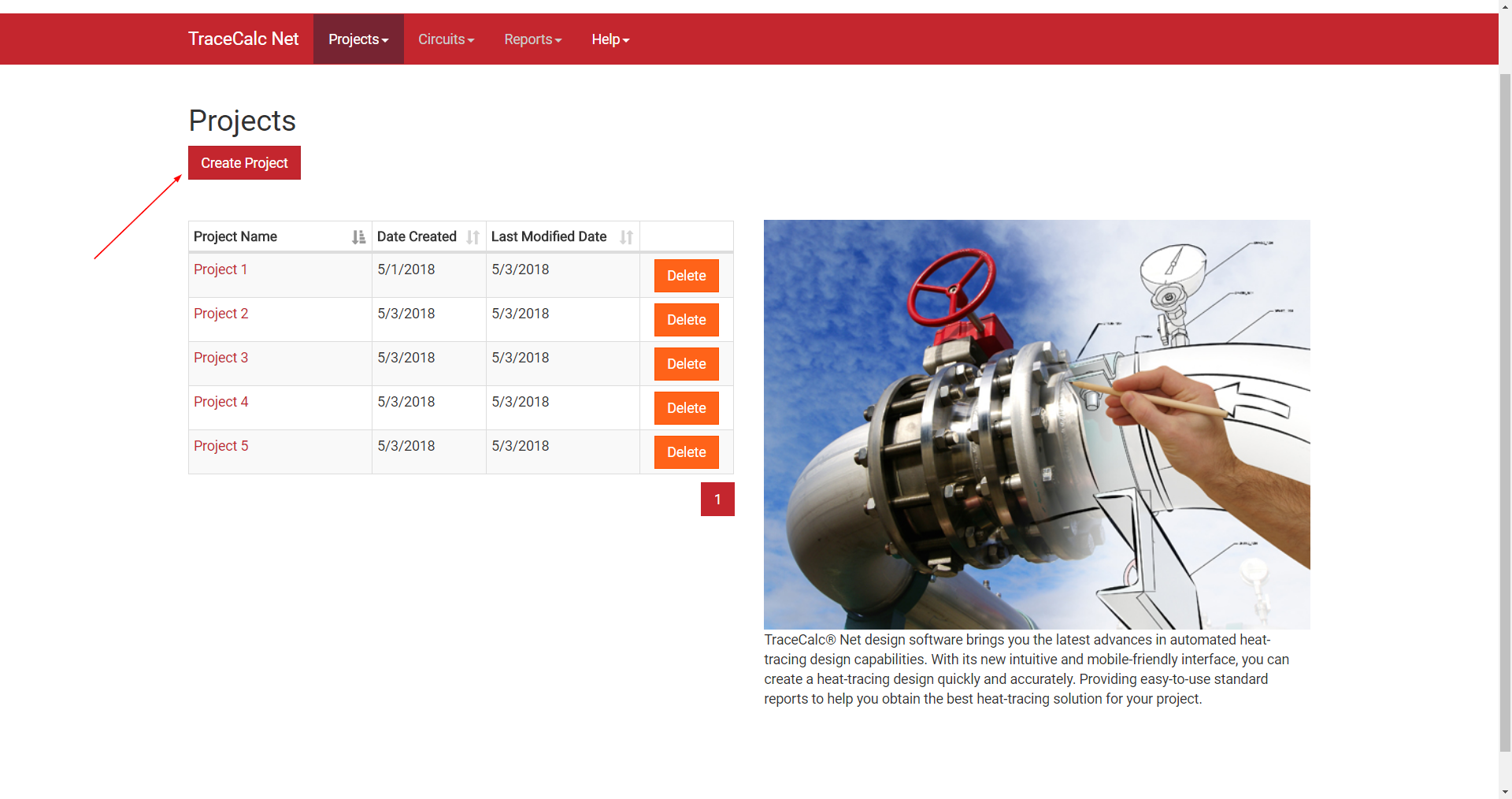
Once logged into the TraceCalc Net web application, click “Create Project”. This will take you to the Create Project form.
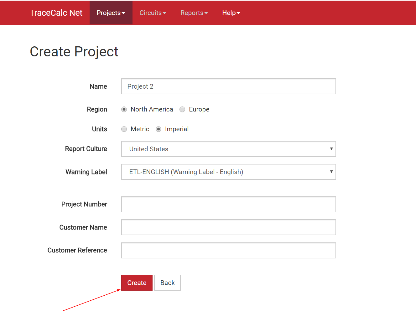
Enter the appropriate information into each field and click “Create”. This will take you to the Circuit Settings form.
Remark: Region will drive product selection and associated certification.
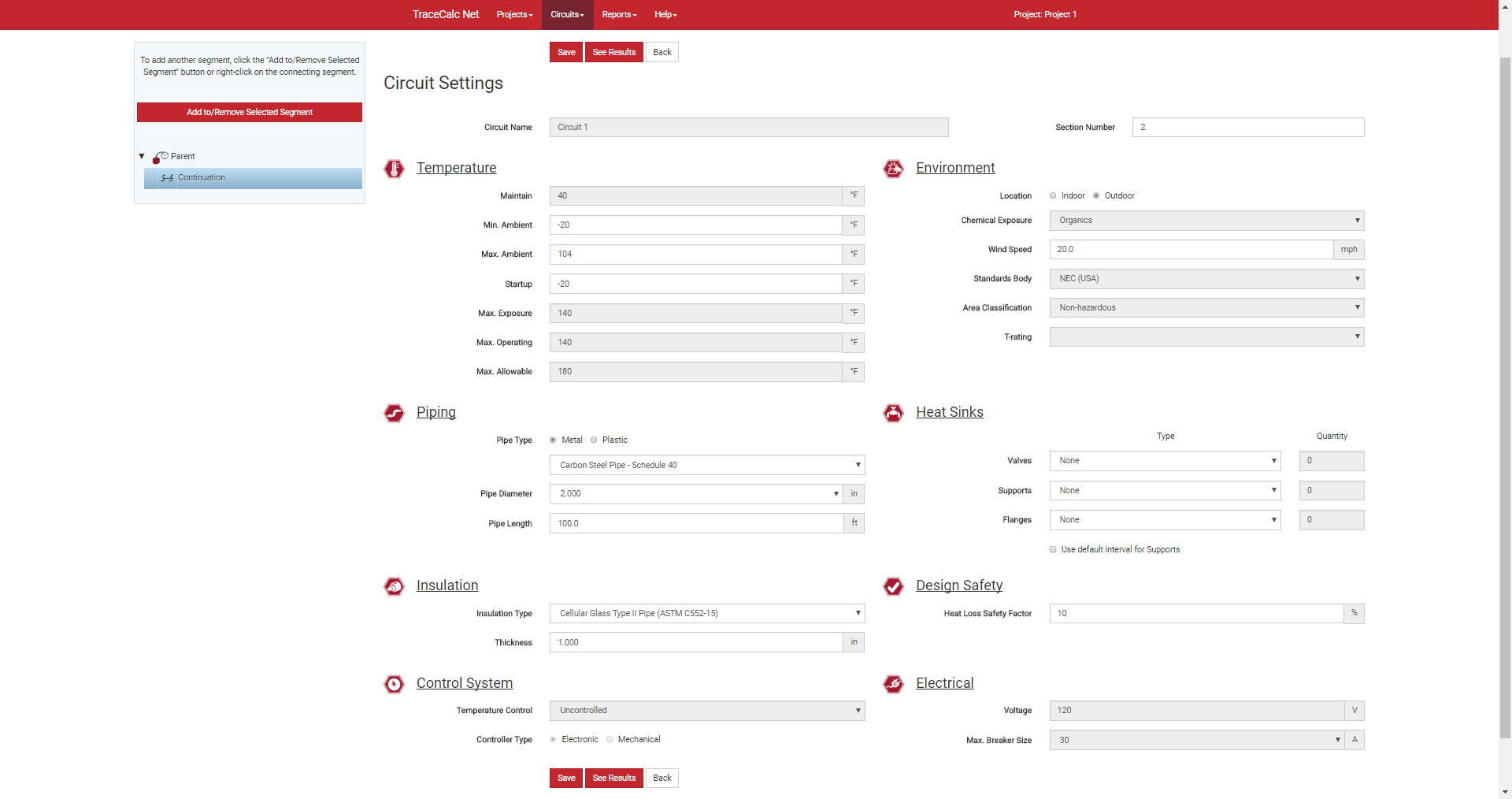
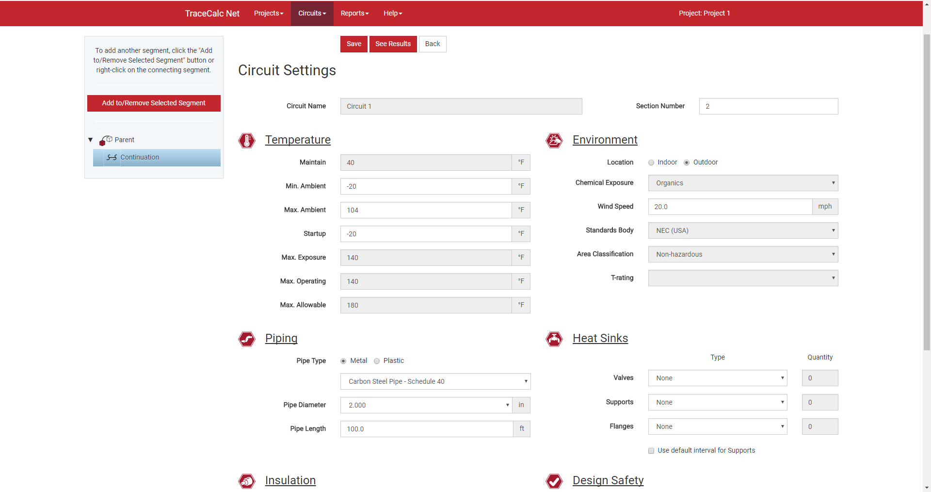
Complete all fields of the form based on your design conditions, the electrical/environmental parameters, and the control system you require. Click “Save”.

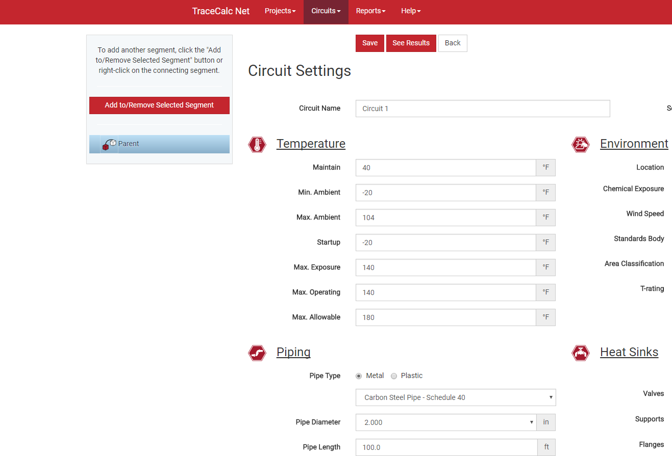
If more than one segment is required for the circuit, click “Add to/Remove Selected Segment” and select the appropriate one from the drop-down menu.
Once a child has been created, you will be able to update the circuit settings for that segment. Please note, some of the entry fields will be greyed out. These fields are controlled by the parent and cannot be modified at the child level.
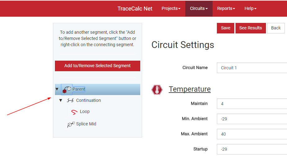
New segments can be added to both the parent segment and other child segments. You can switch between them by clicking on the segment tree and on the left side of the form. Always remember to click “Save” before adding a new segment or switching between existing ones. If you wish to delete a segment, select “Remove” from the drop-down.
Once you have completed the circuit settings for all necessary segments, click “See Results” to view design results. If your circuit has multiple segments, click on the different segments in the segment tree to view design results for each one.
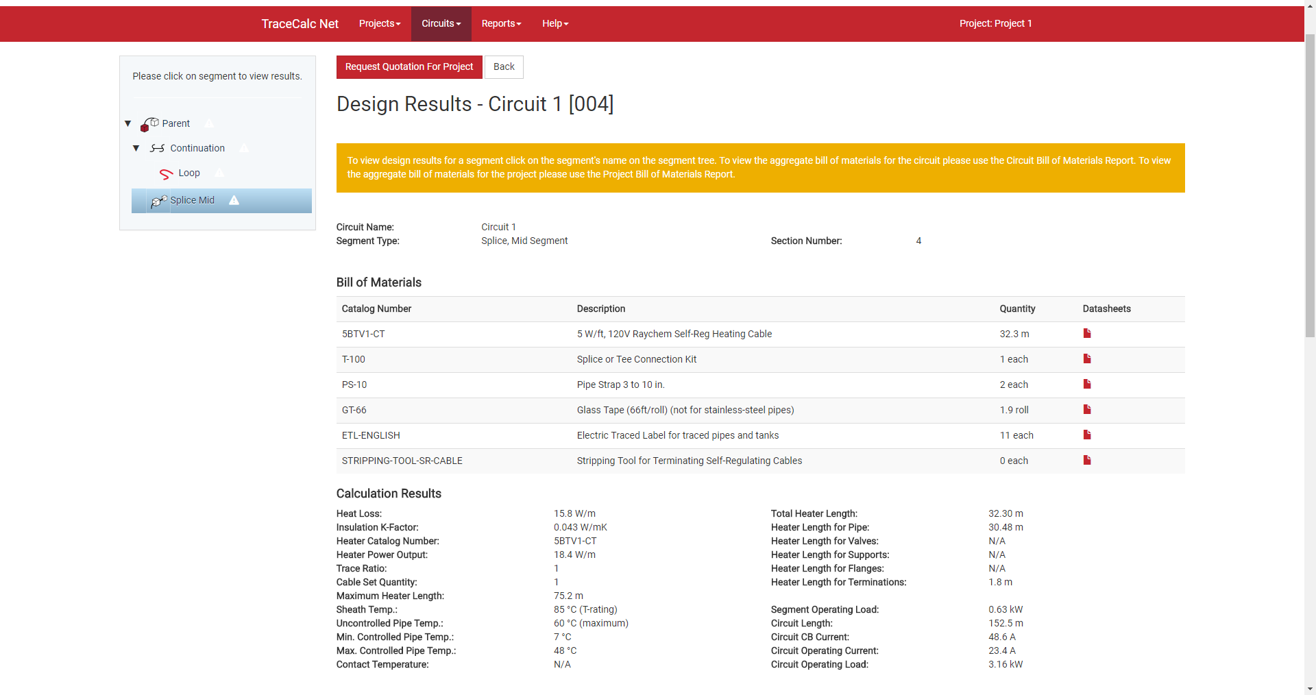
After reviewing these results, you may either click “Back” to return to the Circuit Settings form, or you may click “Request Quotation for this Project” to open the Quotation Request form.
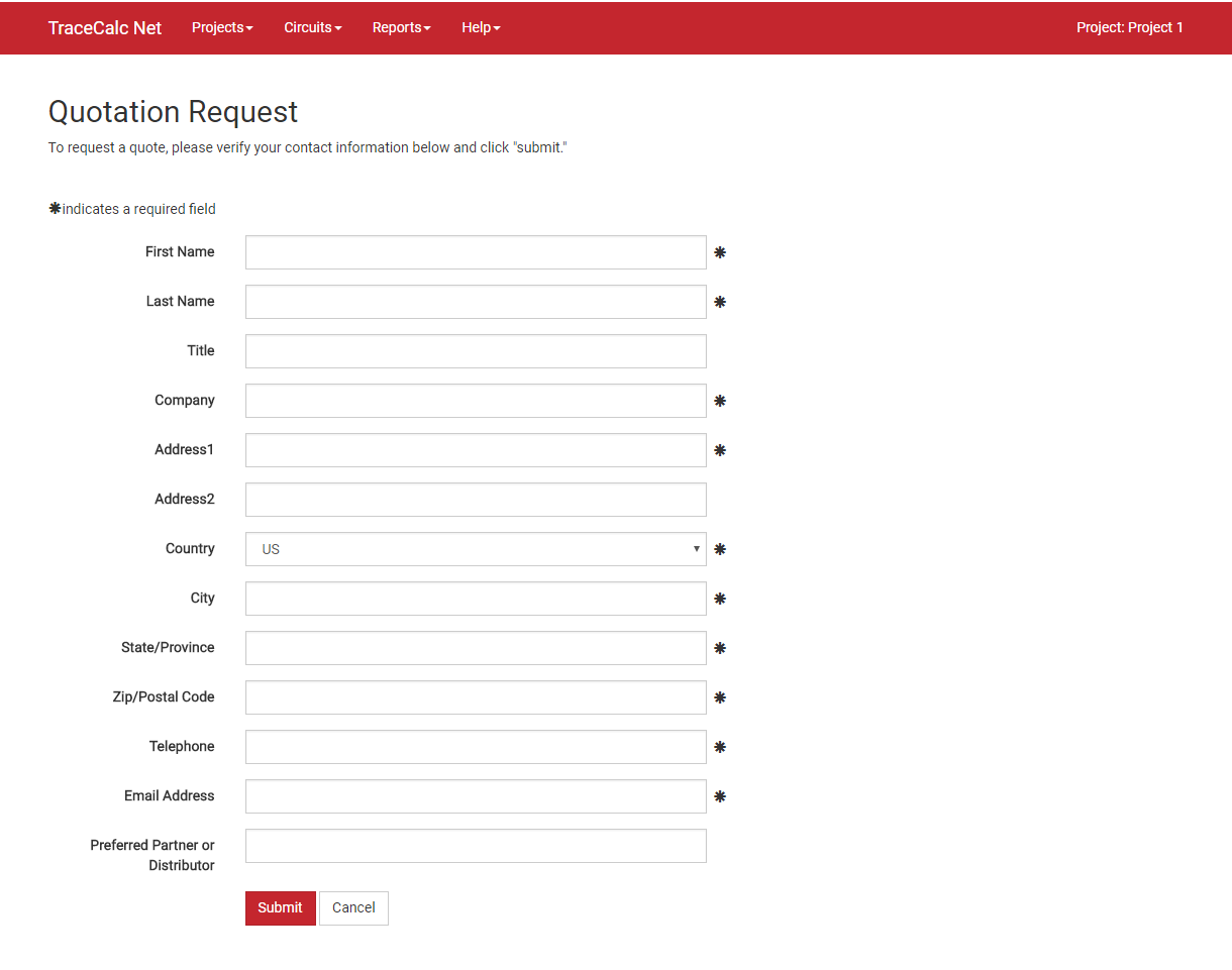
Complete all required fields and click “Submit”. Please note, the City, State/Province, and Zip/Postal Code fields will be used to identify the closest sales representative to your location. Once your request has been submitted to nVent, you will be contacted within 2 business days.
 NavigationIndex
Projects
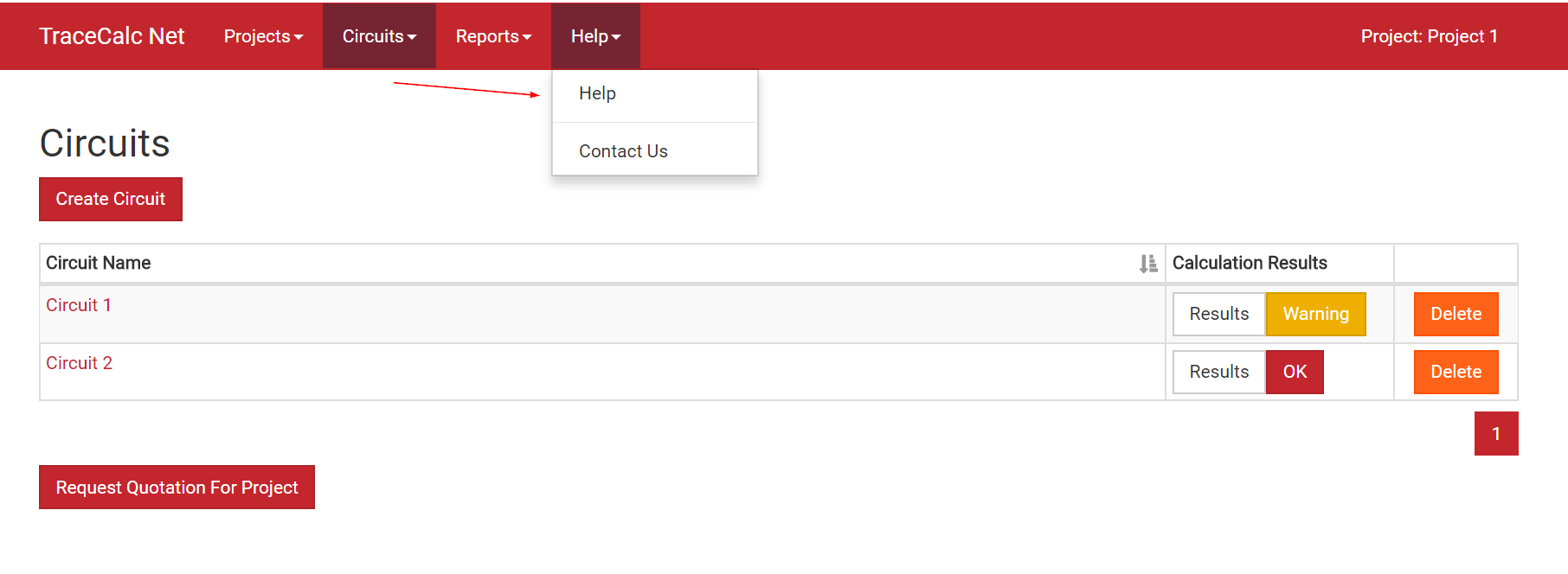
Once logged into TraceCalc Net, you will notice 4 menu options at the top of your screen. Please note that while you are on the Projects page, the only menus available to you will be “Projects” and “Help”. To enable to other menu selections you will have to open up a circuit list or specific circuit.
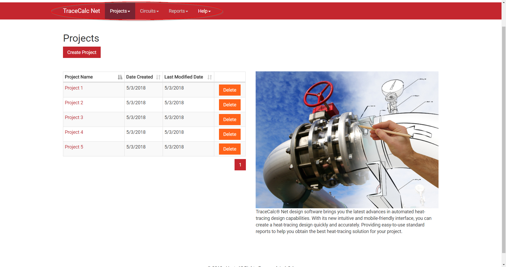
Once logged into TraceCalc Net, you will notice 4 menu options at the top of your screen. Please note that while you are on the Projects page, the only menus available to you will be “Projects” and “Help”. To enable to other menu selections you will have to open up a circuit list or specific circuit.
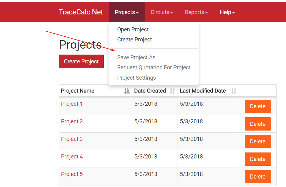
Open Project: Use this selection to open a project.
Create Project: Use this selection to create a new project.
Once you have selected a project, the remaining options will be enabled for you.
Save Project As: Use this selection to save a new copy of an existing project.
Request Quotation for Project: Use this to send a quote request to a sales representative.
Project Settings: Use this to update your project settings.
Project List: This will direct you back to the listing of all projects you’ve created in TraceCalc Net
Circuits
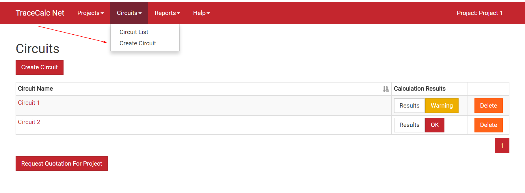
After you select a project from the Projects list, you will be taken to the appropriate Circuits List. From here, you can perform the following tasks:
Create a circuit or request a quote for the project.
Access the circuit settings form by clicking on the circuit name.
View circuit calculation results by click on “Result”.
Delete a circuit.
The circuit menu itself will give you two options to select:
Circuit List: This will direct you back to the listing of all circuits for your project.
Create Circuit: Use this to create a new circuit for your project.
Reports
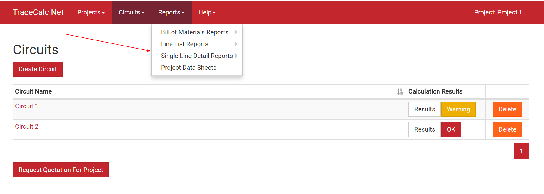
From the circuit list, you will also be able to access a number of different reports:
Project Bill of Materials Report: This report will list catalog numbers, product descriptions and quantities for all materials in your project.
Project Data Sheets: This will provide you a zip file with data sheets for all products included in your bill of materials.
Project Single Line Detail Report: This report will collect the calculation results, bill of materials, and input parameters for all circuits in your project.
Project Summary Line List Report: This report will collect input data and calculation results for each specific line within your project (temperatures, pipe length/diameter, insulation type/thickness, pipe heat loss, heater power output/length, heater catalog number, etc.)
Project Electrical Line List Report: This report will collect the electrical data for each line within your project (circuit breaker sizing, circuit operating load, circuit operating voltage, etc.)
Circuit Single Line Detail Report: You must select a circuit to run this report. It will collect the calculation results, bill of materials, and input parameters for a single circuit in your project.
Help
From the circuit list, you will also be able to access a number of different reports:
Help: This will access the online help file.
Contact Us: This will allow you to send a question to nVent.
 Project SettingsIndex
Project Name
Enter a name for your heat-tracing design project. This field accepts 50 characters. The project name will appear on all reports generated by the program.
Units
Choose either Imperial or Metric units.
Report Language
Select a language from the language list. All text displayed in reports will be in the chosen language.
Warning Label
Select from the list of Warning Label options.
Project Number
Enter a number for your heat-tracing design project. This field accepts 30 characters. The project number will appear on reports generated by the program.
Customer Name
Enter the name of the customer who is the recipient of the heat-tracing design project. This field accepts 30 characters. The customer name will appear on all reports generated by the program.
Customer Reference
Enter the customer reference number that identifies the customer of the heat-tracing design project. This field accepts 50 characters. The customer reference number will appear on all reports generated by the program.
 LINE TYPEIndex
Line Type describes the position of the line in a heat-tracing circuit and is only important for circuits involving multiple pipe segments. You must define the Line Type when you add a line because the program uses this information to determine which components to include for each segment. For example, properly assigning the line type to each of three cable segments connected to a tee kit ensures that only one tee kit and two end seals are included in the bill of materials, and not three power kits and three end seals. If you are not comfortable with this new feature, you can simply define all lines as “Parent lines” and then manually group circuits and adjust component quantities.
Remember, you do not need to calculate the number of components required for your design configuration. You only need to properly define the Line Type for each line and TraceCalc Net will automatically determine the number of associated components.
![]() Parent
Parent
If you add a line, the default Line Type is “Parent”. A Parent line will have a power connection kit. It may or may not have an end seal kit, depending on what types of child lines it may have.
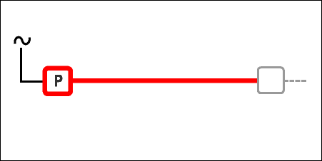
The program recognizes multiple line types. If the heat-tracing circuit consists of just one segment, i.e. a continuous length of heating cable from power point to end seal, it can be simply defined as a “Parent” Line Type. Each new line added to a project is also assigned a Parent Line Type by default until, and unless, you change it as described above. A parent line always includes a power kit but may or may not include an end seal depending on whether there are other lines associated with it.
If there are other lines associated with the parent, they are referred to as child lines throughout this manual. A child may be thought of as a subline. It is a user-defined identification of a pipe segment for the purposes of organizing or simplifying the heat-tracing design. It is a segment of a pipe system that is somehow connected to, and is typically downstream of, a parent segment for either electrical or flow purposes. For instance, a branch of a fire water line could be a “child” of the water line. The child takes on the design-related parameters of the parent unless you override them. For instance, while it may optionally have the same ambient conditions as the parent, it will always have the same power-related conditions as the parent, i.e., the same voltage, circuit breaker rating, etc., because it is powered through the same circuit breaker.
A wide range of circuit configurations can be created using the various child Line Types described below.
![]() Power, Parallel
Power, Parallel
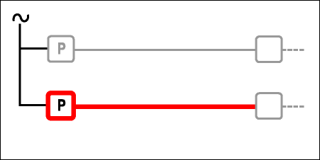
Power, Parallel is a line with its own power connection kit electrically connected to the same circuit breaker as the parent. It may also include an end seal, depending on the design (if no other lines are connected, it will include the end seal).
![]() Power, Splice
Power, Splice
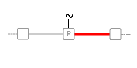
Power, Splice is a line that is powered from the same power connection kit as the parent. For bill of materials purposes, it does not include a power kit but may include an end seal depending on the design (if no other lines are connected, it will include the end seal).
![]() Power Tee
Power Tee
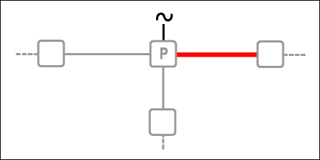
Power, Tee is a line that is one of two other lines powered from the same power connection kit as the parent. For bill of materials purposes, it does not include a power kit but typically an end seal depending on the design. A powered tee box includes at least a parent line as well as two power-tees. If you don’t define a complete set, TraceCalc Net will not be able to determine a complete Bill of Materials. If you define a parent with just one power-tee child, it will be similar to a power splice and just require a power box that could also be used for a tee.
)
![]() Splice, End Segment
Splice, End Segment
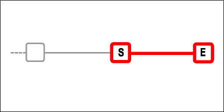
Splice, End Segment is a line that is spliced to one other segment. Its power comes from the other segment, not directly from the power source. For bill of materials purposes, it includes a splice kit and typically includes an end seal depending on the design.
![]() Splice, Mid Segment
Splice, Mid Segment
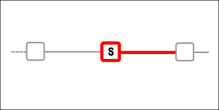
Splice, Mid Segment is a line that is spliced to another segment at each end. Its power comes from one of the other segments, not directly from the power source. For bill of materials purposes, it includes a splice kit but does not include an end seal. If no other lines are connected, don’t use the mid-segment, but the end-segment. Otherwise your Bill of Materials will not include the required end seal.
![]() Tee, End Segment
Tee, End Segment
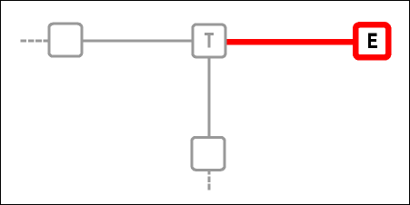
Tee, End Segment is a line that is connected to a tee. The difference from the Tee-mid segment is that the end segment does not include the tee-kit. For Bill of Materials purposes, it typically just includes an end seal depending on the design.
![]() Tee, Mid Segment
Tee, Mid Segment
Tee, Mid Segment is a line that is connected to a tee. Its power comes from its parent. For Bill of Materials purposes, it includes a tee kit and typically includes an end seal depending on the design.
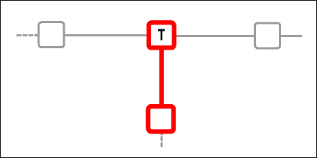
![]() Continuation
Continuation
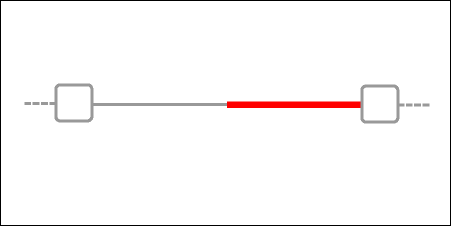
Continuation is a line that is a segment of another line, but which needs to be identified separately for design purposes. The Bill of Materials does not include any components; they are included in its parent line. This is a very useful way to handle situations where the same pipe has changing design parameters such as diameter, insulation temperature or Ambient temperature, and the designer knows that the same cable will be used.
![]() Loop
Loop
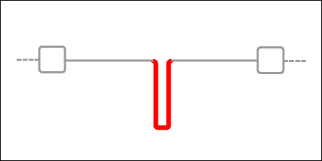
Loop is a line that is a segment of another line, but which needs to be identified separately for design purposes. It returns to its point of origin on the pipe segment. For bill of materials purposes, it does not include any components. This is a useful way to handle short piping tee sections.
 Circuit SettingsIndex
Circuit Name
Choose a name for your circuit and enter here. The name must be unique and not been used before. The maximum length of the name is 50 characters.
Section Number
The purpose of the Section Number is to allow you to use the same Circuit Name for several pipe segments and to differentiate between them by assigning different section numbers. This allows you to develop different heat-tracing designs for different segments of the same pipe.
 PipingIndex
Pipe Type or Material
The material used to make the pipe affects how well the heat transfers from the heating cable to the pipe contents. Since plastic does not conduct heat as well as metal, plastic pipes generally require a heating cable with a higher power output. In plastic pipe applications, aluminum tape must be installed lengthwise along the entire length of the cable to increase heat transfer to the pipe.
The drop down menu allows for a selection of pipe types in different metals and wall thicknesses as well as a set of plastic pipes in different wall thickness and plastic types. Not all plastic pipe types may be represented in the list. In that case, pick a pipe material from the list with a lower thermal conductivity.
For reference K value @ 25 °C, 77 °F:
Fiberglass Reinforced: 0.03 W/mK
Polyethylene (PE): 0.5 W/mK
Polyvinylchloride (PVC): 0.2 W/mK
Pipe Diameter or Size
The larger the pipe, the higher the heat loss and more total wattage is required to offset the heat loss.
The pipe types with references to European standards (e.g. EN, DIN, DN, PN) allow the pipe size to be entered in metric units, even if imperial units were selected. The other pipe types will allow the pipe sizes in imperial units, even if metric units were selected.
The software will propose a solution to compensate the heat loss to maintain the desired temperature under the given design conditions. However the software will not verify the internal temperature distribution and it is up to the user to assess if the solution is appropriate for this application. This is particularly important for large pipe diameters. In these cases, it might be more appropriate to use a low power heater with a multiple trace ratio instead of a high power heater with a single trace ratio.
Contact nVent for assistance.
Pipe Length
Round the lengths up to the next higher foot or 1/10 meter.
 InsulationIndex
Insulation Type
The amount of heat a pipe will lose depends on the pipe size, the difference between pipe and outside temperatures, and the pipe's thermal resistance. Insulation that provides higher thermal resistance will lower the pipe's heat loss. The pipe can then use a heating cable with a lower power output. For larger pipe sizes, this may eliminate the need for more than one run of heating cable.
The insulation types available in the selection list are the most commonly used and the k values are as per the standard indicated in the description.
For reference, these can be found below:
| Temperature | CG TYPE II:2015 | EP:2015 | FE GR1,3:2014 | FE GR2:2014 | RW/MF 1:2015 | RW/MF 4:2015 |
|---|---|---|---|---|---|---|
| -50 °C | 0.036 W/mK | 0.062 W/mK | 0.034 W/mK | 0.034 W/mK | 0.023 W/mK | 0.023 W/mK |
| -25 °C | 0.041 W/mK | 0.066 W/mK | 0.037 W/mK | 0.037 W/mK | 0.026 W/mK | 0.026 W/mK |
| 0 °C | 0.045 W/mK | 0.067 W/mK | 0.039 W/mK | 0.040 W/mK | 0.030 W/mK | 0.030 W/mK |
| 25 °C | 0.049 W/mK | 0.068 W/mK | 0.040 W/mK | 0.043 W/mK | 0.034 W/mK | 0.034 W/mK |
| 50 °C | 0.053 W/mK | 0.070 W/mK | 0.043 W/mK | 0.047 W/mK | 0.038 W/mK | 0.038 W/mK |
| 75 °C | 0.058 W/mK | 0.074 W/mK | 0.044 W/mK | 0.048 W/mK | 0.042 W/mK | 0.042 W/mK |
| 100 °C | 0.064 W/mK | 0.077 W/mK | 0.052 W/mK | 0.047 W/mK | 0.046 W/mK | |
| 125 °C | 0.069 W/mK | 0.081 W/mK | 0.056 W/mK | 0.052 W/mK | 0.050 W/mK | |
| 150 °C | 0.075 W/mK | 0.085 W/mK | 0.061 W/mK | 0.058 W/mK | 0.053 W/mK | |
| 175 °C | 0.083 W/mK | 0.088 W/mK | 0.066 W/mK | 0.059 W/mK | ||
| 200 °C | 0.090 W/mK | 0.091 W/mK | 0.073 W/mK | 0.064 W/mK |
| Temperature | CG TYPE II:2015 | EP:2015 | FE GR1,3:2014 | FE GR2:2014 | RW/MF 1:2015 | RW/MF 4:2015 |
|---|---|---|---|---|---|---|
| -58 °F | 0.250 BTU-in/hr-ft²-°F | 0.430 BTU-in/hr-ft²-°F | 0.236 BTU-in/hr-ft²-°F | 0.236 BTU-in/hr-ft²-°F | 0.159 BTU-in/hr-ft²-°F | 0.159 BTU-in/hr-ft²-°F |
| -13 °F | 0.284 BTU-in/hr-ft²-°F | 0.458 BTU-in/hr-ft²-°F | 0.257 BTU-in/hr-ft²-°F | 0.257 BTU-in/hr-ft²-°F | 0.180 BTU-in/hr-ft²-°F | 0.180 BTU-in/hr-ft²-°F |
| 32 °F | 0.312 BTU-in/hr-ft²-°F | 0.465 BTU-in/hr-ft²-°F | 0.270 BTU-in/hr-ft²-°F | 0.277 BTU-in/hr-ft²-°F | 0.208 BTU-in/hr-ft²-°F | 0.208 BTU-in/hr-ft²-°F |
| 77 °F | 0.340 BTU-in/hr-ft²-°F | 0.471 BTU-in/hr-ft²-°F | 0.277 BTU-in/hr-ft²-°F | 0.298 BTU-in/hr-ft²-°F | 0.236 BTU-in/hr-ft²-°F | 0.236 BTU-in/hr-ft²-°F |
| 122 °F | 0.367 BTU-in/hr-ft²-°F | 0.485 BTU-in/hr-ft²-°F | 0.298 BTU-in/hr-ft²-°F | 0.326 BTU-in/hr-ft²-°F | 0.263 BTU-in/hr-ft²-°F | 0.263 BTU-in/hr-ft²-°F |
| 167 °F | 0.402 BTU-in/hr-ft²-°F | 0.513 BTU-in/hr-ft²-°F | 0.305 BTU-in/hr-ft²-°F | 0.333 BTU-in/hr-ft²-°F | 0.291 BTU-in/hr-ft²-°F | 0.291 BTU-in/hr-ft²-°F |
| 212 °F | 0.444 BTU-in/hr-ft²-°F | 0.534 BTU-in/hr-ft²-°F | 0.361 BTU-in/hr-ft²-°F | 0.326 BTU-in/hr-ft²-°F | 0.319 BTU-in/hr-ft²-°F | |
| 257 °F | 0.478 BTU-in/hr-ft²-°F | 0.562 BTU-in/hr-ft²-°F | 0.388 BTU-in/hr-ft²-°F | 0.361 BTU-in/hr-ft²-°F | 0.347 BTU-in/hr-ft²-°F | |
| 302 °F | 0.520 BTU-in/hr-ft²-°F | 0.589 BTU-in/hr-ft²-°F | 0.423 BTU-in/hr-ft²-°F | 0.402 BTU-in/hr-ft²-°F | 0.367 BTU-in/hr-ft²-°F | |
| 347 °F | 0.575 BTU-in/hr-ft²-°F | 0.610 BTU-in/hr-ft²-°F | 0.458 BTU-in/hr-ft²-°F | 0.409 BTU-in/hr-ft²-°F | ||
| 392 °F | 0.624 BTU-in/hr-ft²-°F | 0.631 BTU-in/hr-ft²-°F | 0.506 BTU-in/hr-ft²-°F | 0.444 BTU-in/hr-ft²-°F |
In case the insulation material to be used is not available from the list, pick one with closest higher K value.
Remark: In case rigid insulation would be used, it is important to oversize the insulation in order to accommodate the installation of the heating cable. This option is not supported in this software.
Insulation Thickness
The thickness of the pipe's insulation helps to determine pipe heat loss, as well as the type of heating cable required for the application. Using thicker insulation means the pipe will have a lower heat loss and can use a heating cable with a lower power output. For larger pipe sizes, this may eliminate the need for more than one run of heating cable.
 Heat SinksIndex
Valve Type and Quantity
Since additional heating cable will be required to make up for the heat loss at the valve, each valve increases the length of heating cable required. The software allows the selection of different types of valves using different design principles and quantities.
A first possibility is to select between light and heavy valves, heavy valves both flanged or welded. Upon selecting these types, the software will use fixed adder tables to compensate for the additional heat loss. The adder tables have been defined by years of experience for the most commonly used light and heavy valve types. However, it is up to the user to assess the applicability of the adders for his purpose.
A second possibility is to use the typical valve or typical valve with actuator. For these types, the software will calculate the additional heat loss of the valve which is mainly driven by the handle which is sticking out of the insulation (typical valve) and potentially the presence of an electric or pneumatic actuator which is also connected to the valve body (typical valve with actuator).
The calculations are based on most common dimensions of valves, handles and actuators but it is up to the user to assess whether the calculated heat loss is applicable to the specific type of valve he is using.
Fixed adder tables:
| Absolute Heater Length | |||||||
|---|---|---|---|---|---|---|---|
| Pipe Diameter | 02FIXV1 - Light Valve (screwed/welded) | 02FIXV3 - Light Valve (flanged) | 02FIXV4 - Heavy Valve (flanged) | ||||
| in | mm | ft | m | ft | m | ft | m |
| 0.125 | 6 | 0.5 | 0.15 | 0.5 | 0.15 | 0.5 | 0.15 |
| 0.25 | 8 | 0.5 | 0.15 | 0.5 | 0.15 | 0.5 | 0.15 |
| 0.375 | 9 | 0.5 | 0.15 | 0.8 | 0.24 | 0.8 | 0.24 |
| 0.5 | 15 | 1.0 | 0.3 | 1.0 | 0.3 | 1.0 | 0.3 |
| 0.75 | 20 | 1.0 | 0.3 | 1.5 | 0.46 | 1.5 | 0.46 |
| 1 | 25 | 1.0 | 0.3 | 2.0 | 0.61 | 2.0 | 0.61 |
| 1.25 | 32 | 1.0 | 0.3 | 2.0 | 0.61 | 2.5 | 0.76 |
| 1.5 | 40 | 1.5 | 0.46 | 2.5 | 0.76 | 3.0 | 0.91 |
| 2 | 50 | 2.0 | 0.61 | 2.5 | 0.76 | 3.5 | 1.07 |
| 2.5 | 65 | 2.0 | 0.61 | 2.5 | 0.76 | 3.5 | 1.07 |
| 3 | 80 | 2.5 | 0.76 | 3.0 | 0.91 | 4.0 | 1.22 |
| 3.5 | 90 | 2.5 | 0.76 | 3.0 | 0.91 | 4.5 | 1.37 |
| 4 | 100 | 3.0 | 0.91 | 4.0 | 1.22 | 5.0 | 1.52 |
| 5 | 125 | 3.0 | 0.91 | 4.0 | 1.22 | 5.5 | 1.68 |
| 6 | 150 | 3.5 | 1.07 | 5.0 | 1.52 | 6.0 | 1.83 |
| 8 | 200 | 4.0 | 1.22 | 7.0 | 2.13 | 8.0 | 2.44 |
| 10 | 250 | 5.0 | 1.52 | 8.0 | 2.44 | 10.0 | 3.05 |
| 12 | 300 | 6.0 | 1.83 | 9.0 | 2.74 | 12.0 | 3.66 |
| 14 | 350 | 7.0 | 2.13 | 10.0 | 3.05 | 14.0 | 4.27 |
| 16 | 400 | 8.0 | 2.44 | 11.0 | 3.35 | 16.0 | 4.88 |
| 18 | 450 | 9.0 | 2.74 | 12.0 | 3.66 | 18.0 | 5.49 |
| 20 | 500 | 10.0 | 3.05 | 13.0 | 3.96 | 20.0 | 6.1 |
| 22 | 550 | 11.0 | 3.35 | 14.0 | 4.27 | 22.0 | 6.71 |
| 24 | 600 | 12.0 | 3.66 | 15.0 | 4.57 | 24.0 | 7.32 |
| 26 | 650 | 13.0 | 3.96 | 15.0 | 4.57 | 26.0 | 7.92 |
| 28 | 700 | 14.0 | 4.27 | 15.0 | 4.57 | 28.0 | 8.53 |
| 30 | 750 | 15.0 | 4.57 | 18.0 | 5.49 | 30.0 | 9.14 |
| 32 | 800 | 16.0 | 4.88 | 18.0 | 5.49 | 32.0 | 9.75 |
| 34 | 850 | 17.0 | 5.18 | 18.0 | 5.49 | 34.0 | 10.36 |
| 36 | 900 | 18.0 | 5.49 | 20.0 | 6.1 | 36.0 | 10.97 |
| 38 | 950 | 19.0 | 5.79 | 20.0 | 6.1 | 38.0 | 11.58 |
| 40 | 1000 | 20.0 | 6.1 | 22.0 | 6.71 | 40.0 | 12.19 |
| 42 | 1050 | 21.0 | 6.4 | 24.0 | 7.32 | 42.0 | 12.8 |
| 44 | 1100 | 22.0 | 6.71 | 26.0 | 7.92 | 44.0 | 13.41 |
| 46 | 1150 | 23.0 | 7.01 | 28.0 | 8.53 | 46.0 | 14.02 |
| 48 | 1200 | 24.0 | 7.32 | 30.0 | 9.14 | 48.0 | 14.63 |
| 52 | 1300 | 26.0 | 7.92 | 32.0 | 9.75 | 52.0 | 15.85 |
| 56 | 1400 | 28.0 | 8.53 | 34.0 | 10.36 | 56.0 | 17.07 |
| 60 | 1500 | 30.0 | 9.14 | 36.0 | 10.97 | 60.0 | 18.29 |
| 64 | 1600 | 32.0 | 9.75 | 38.0 | 11.58 | 64.0 | 19.51 |
| 68 | 1700 | 34.0 | 10.36 | 40.0 | 12.19 | 68.0 | 20.73 |
| 72 | 1800 | 36.0 | 10.97 | 42.0 | 12.8 | 72.0 | 21.95 |
Support Type and Quantity
Since supports are heat sinks, it increases the heat loss of the system and additional heating cable will be required to make up for this. Hence each support increases the length of heating cable required.
There are a variety of supports available. If you are not sure of the type to select, select typical support in this field as it provides a good estimation based on the most common support types with respect to the pipe diameter. One can also be more specific and select a type from the list: the selection ranges from hangers to welded shoes in various dimensions as indicated in their descriptions. The heat loss for the supports is determined by the fin effect. However, it remains up to the user to assess the applicability of the adders for his purpose.
Flange Type and Quantity
Flanges increase the overall diameter increasing the heat loss Additional cable length is needed to compensate. . Select the flange and enter the number of flange pairs in the piping system required.
There is one flange adder design available: Typical Flange (3xDiam.).
The adder table has been defined by years of experience for the most commonly used flange types. However, it is up to the user to assess the applicability of the adders for his purpose.
Fixed adder table:
| Absolute Heater Length | |||
|---|---|---|---|
| Pipe Diameter | FLANGE (3XD) - Typical Flange (3xDiam.) | ||
| in | mm | ft | m |
| 0.125 | 6 | 0.3 | 0.09 |
| 0.25 | 8 | 0.3 | 0.09 |
| 0.375 | 9 | 0.3 | 0.09 |
| 0.5 | 15 | 0.3 | 0.09 |
| 0.75 | 20 | 0.3 | 0.09 |
| 1 | 25 | 0.3 | 0.09 |
| 1.25 | 32 | 0.3 | 0.09 |
| 1.5 | 40 | 0.7 | 0.21 |
| 2 | 50 | 0.7 | 0.21 |
| 2.5 | 65 | 0.7 | 0.21 |
| 3 | 80 | 0.7 | 0.21 |
| 3.5 | 90 | 0.7 | 0.21 |
| 4 | 100 | 0.7 | 0.21 |
| 5 | 125 | 0.7 | 0.21 |
| 6 | 150 | 0.7 | 0.21 |
| 8 | 200 | 0.7 | 0.21 |
| 10 | 250 | 1.0 | 0.3 |
| 12 | 300 | 1.0 | 0.3 |
| 14 | 350 | 1.0 | 0.3 |
| 16 | 400 | 1.0 | 0.3 |
| 18 | 450 | 1.0 | 0.3 |
| 20 | 500 | 1.3 | 0.4 |
| 22 | 550 | 1.3 | 0.4 |
| 24 | 600 | 1.3 | 0.4 |
| 26 | 650 | 1.3 | 0.4 |
| 28 | 700 | 1.6 | 0.49 |
| 30 | 750 | 1.6 | 0.49 |
| 32 | 800 | 1.6 | 0.49 |
| 34 | 850 | 1.6 | 0.49 |
| 36 | 900 | 1.6 | 0.49 |
| 38 | 950 | 1.6 | 0.49 |
| 40 | 1000 | 1.6 | 0.49 |
| 42 | 1050 | 1.6 | 0.49 |
| 44 | 1100 | 1.6 | 0.49 |
| 46 | 1150 | 1.6 | 0.49 |
| 48 | 1200 | 1.6 | 0.49 |
| 52 | 1300 | 2.0 | 0.61 |
| 56 | 1400 | 2.0 | 0.61 |
| 60 | 1500 | 2.3 | 0.7 |
| 64 | 1600 | 2.3 | 0.7 |
| 68 | 1700 | 2.6 | 0.79 |
| 72 | 1800 | 2.6 | 0.79 |
 TemperatureIndex
Maintain
The Maintain temperature is the desired temperature at which you want to maintain the pipe by the use of heat tracing.
Minimum Ambient
The minimum ambient temperature is the lowest temperature expected to occur at the design site. The minimum ambient temperature for indoor locations should be the lowest indoor temperature, irrespective of the corresponding minimum outdoor ambient temperature.
Maximum Ambient
The Maximum Ambient temperature is the highest temperature expected to occur at the design site. The Maximum Ambient temperature for indoor locations should be the highest indoor temperature irrespective of the maximum outdoor ambient temperature.
Startup
The Startup Temperature is the lowest pipe or equipment temperature expected when the heating cables are switched on. It might be the Minimum Ambient temperature, but realistically will often be higher.
Maximum Heater Exposure
The Maximum Heater Exposure temperature is the maximum temperature to which the heating cable may be exposed intermittently. Intermittent is defined as high-temperature excursions of not more than 48 hours in duration, with total cumulative exposure of less than 1000 hours. This value is used to ensure that the selected heater is not affected negatively by these temperature excursions. TraceCalc Net will igore this temperature for the purpose of predicting maximum heating cable sheath temperatures. In many applications the Maximum Heater Exposure temperature will be the same as the Maximum Operating temperature.
Maximum Pipe Operating
The Maximum Operating temperature is the highest temperature of the heat-traced fluid during normal process operating conditions. Excursions of less than 1000 hours cumulative may be ignored. TraceCalc Net will select a suitable heating cable assuming that the Maximum Operating temperature is the highest continuous (for greater than 1000 hours) exposure temperature for the heating cable whether energized or de-energized (depending on the control method). This temperature is included for the purpose of predicting maximum heating cable sheath temperatures. The Maximum Operating temperature may be the same as the Maintain temperature, but it could be considerably higher. For example, when a process pipe operates at a high Operating temperature but the heat tracing is only required to prevent the pipe from freezing during shutdown conditions. In this case, the Maintain temperature is only slightly above the freezing temperature of the fluid.
Maximum Allowable
The Maximum Allowable temperature is the maximum temperature permitted by the user for the process/fluid or piping. The program uses temperature to determine whether temperature controls are required. The value you enter should be the lowest value of the fluid degradation temperature, the piping expansion temperature, or the piping material withstand temperature (especially in the case of plastic piping). For hazardous locations, the maximum temperature ratings are entered separately as an auto-ignition temperature and T-rating.
 ElectricalIndex
Voltage
Self-Heating cables are normally powered at voltages between 190 V and 277 V for Europe and 100 V and 277 V for North America. Constant wattage zone heater technology has a voltage range of 190 V to 480 V for Europe and 120 V and 480 V for North America. Using higher voltages allows you to use longer circuit lengths on a single circuit breaker.
Max. Breaker Size
The amperage rating of the circuit breaker dictates the maximum length of heating cable that can be run on one circuit breaker.
 EnvironmentIndex
Location
Specify whether the heat-tracing installation will be Indoor or Outdoor. If it is Outdoor, the wind speed is requested. If it is Indoor, the heat loss is adjusted as a result of no wind. If the heat tracing is in an indoor area, but still subjected to wind, such as a loading bay, it is advisable to specify the application as Outdoor.
Chemical Exposure
The chemicals to which the heating cable may be exposed determine the type of outer jacket to be used for the heating cable. The choice can be no chemical exposure, organics, or non-organics. If the exposure is to both organics & non-organics, select organics,
Heat Loss Safety Factor
The HL Safety Factor (heat loss safety factor) is a user-specified increase to the calculated heat loss by a specified percentage to ensure that the heating cable provides extra power. It is one way to compensate for important design variables that cannot be controlled or quantified.
While 10% is a typical factor for designs at low or moderate temperatures, for higher temperatures, many material properties, installation variables, and heat transfer processes become more important. To compensate for these additional potential heat loss factors, which are difficult to predict or quantify accurately, we recommend higher safety factors as shown below:
Below 150°C (300°F)-- 10%
Up to 260°C (500°F)-- 25%
Above 260°C (500°F)-- 50% or more depending on the application
Keep in mind that this is not the only safety factor incorporated in your design. There are other safety factors incorporated automatically in the design, such as a conservative Minimum Ambient temperature, the minimum power output of the heating cables, the conservative thermal conductivity of the insulation and other variables. A high value should not be relied upon to compensate for extreme changes from the initial design conditions, such as wet or improperly installed insulation.
Standards Body
You must select the Standard Body from the list of choices available. You can select from US, CANADA, and CENELEC¹. This enables the program to only select products with the appropriate certifications.
US represents FM²,UL³ or other equivalent Nationally Recognized Testing Laboratories (NRTL).
CANADA represents CSA⁴.
CENELEC represents European approval agencies such as BASEEFA, FIMCO, KEMA, LCIE, NEMKO, PTB, SEMKO, and so on.
¹ CENELEC = European Committee for Electrotechnical Standardization. An approval organization that sets industrial safety standards.
² FM = Factory Mutual Research Corporation. An approval organization that sets industrial safety standards.
³ UL = Underwriters Laboratory. An approval organization that sets industrial safety standards.
⁴ CSA= Canadian Standards Association. An approval organization that sets industrial safety standards.
Area Classification
The user can specify whether the heating cable is designed for non-hazardous (ordinary area) or hazardous locations. Non-hazardous or ordinary area is an area where explosive or flammable materials are not present. Hazardous locations are those in which flammable gases, vapors, airborne dusts, or combustible fibers may be present in quantities sufficient to produce explosion or ignition. TraceCalc Net provides some common choices of hazardous locations.
For NEC(US)/CEC(CANADA), the choices are Non-hazardous, Class I Division 1 Gas Group A, Class I Division 1 Gas Group B, Class I Division 1 Gas Group C, Class I Division 1 Gas Group D, Class I Division 2 Gas Group A, Class I Division 2 Gas Group B, Class I Division 2 Gas Group C, Class I Division 2 Gas Group D, Class II Division 1 Dust Group E, Class II Division 1 Dust Group F, Class II Division 1 Dust Group G, Class II Division 2 Dust Group E, Class II Division 2 Dust Group F, Class II Division 2 Dust Group G, Class III Division 1, Class III Division 2, Class I Zone 1, and Class I Zone 2.
For CENELEC(Europe), the choices are Non-hazardous, Zone 1 (Gas), Zone 2 (Gas), Zone 21 (Dust), and Zone 22 (Dust).
Class I = North American classification for Hazardous Areas where the explosive danger consists of flammable gases or vapors.
Division 2 = Terminology used for classification of an industrial area in which flammable gases or combustible dust will only be present under abnormal conditions. Refer to the NEC for a detailed definition.
Zone 1 = Terminology used for classification of an industrial area in which an explosive Gas atmosphere is likely to exist under normal operation. (Refer to the NEC, Article 505, and IEC 79-10 (1995) [B12] for a detailed definition.)
Zone 21 = Same as Zone 1 but for explosive Dust atmosphere
Zone 2 = Terminology used for classification of an industrial area in which an explosive Gas atmosphere is not likely to occur in normal operation, and if they do, they will exist only for a short period. (Refer to the NEC, Article 505, and IEC 79-10 (1995) [B12] for a detailed definition.)
Zone 22 = Same as Zone 2 but for explosive Dust atmosphere
T-rating
Standards associations have established the T-rating, or temperature rating, as a means of classifying electrical equipment based on the maximum temperature an exposed surface may attain. The T-rating is identified as the “Temperature Identification Number” in the National Electrical Code (U.S.), as the “Temperature Code” in the Canadian Electrical Code, and as the “Temperature Class Number” in IEC standards. The purpose of the T-rating is to ensure that electrical equipment does not exceed the auto-ignition temperature¹ of flammables that might be present in a hazardous location.
¹ Auto-ignition temperature (AIT): The AIT is the minimum temperature required to cause self-sustained combustion, independent of a flame or a heated element. This is different from the flash point of a liquid, which is the lowest temperature at which the liquid gives off sufficient vapor to form an ignitable mixture with air near the surface of the liquid or within the vessel used. The flash point of gasoline is -50ºF (-45°C) and the AIT is 536ºF (280°C).
 Control and Monitoring OptionsIndex
Temperature Control
Uncontrolled: No additional temperature control device. This method uses the heating cable's self-regulating properties as the only form of control. It translates to lowest installed cost but highest operating cost.
Ambient sensing - standard: A control method where the heating cable system power is controlled by input from a temperature sensor measuring the ambient temperature. A suitable temperature controller of the desired technology (mechanical or electronic) will be added to the BOM.
Ambient sensing - proportional (PASC): The power to the heat tracing is proportioned based upon on the ambient temperature. If the ambient temperature is at or below the “minimum design ambient” +1 2/3°C the heaters will be on 100%. If the measured ambient is at or above the “maintain temperature” –1 2/3°C the heaters will be on 0%. For any measured ambient between “minimum design ambient” and “maintain temperature,” the heaters will be on a percentage of the time equal to (maintain temperature – measured ambient) / (maintain temperature – minimum design temperature).
Line Sensing: A control method where the heating cable system power is controlled by input from one or more temperature sensor(s) measuring the temperature of the pipe or equipment under the thermal insulation at specific representative locations.
Controller Type
A device that regulates the heat-tracing system by comparing the signal from a sensor to a predetermined value and adjusts its output accordingly. Controllers that regulate temperature are referred to as temperature controllers or thermostats. Temperature sensors can be mechanical (bulb and capillary, bimetallic) or electronic (thermocouple, RTD, thermistor).